
Purpose:
Genesis Sync (TraceNet Sync) serves various purposes, including setting up a new controller, uploading drawings to the HMI, replacing or adding components to the panel, and making mass programming modifications. It's essential to use the latest version of Genesis Sync at all times.
Resources:
Genesis Sync (TraceNet Sync) - Version 1.4.38
This may not be the latest version of TraceNet Sync.
Menu Items:
- Network View: Allows configuring global settings and network communications for the control panel.
- Hardware View: Enables assigning CAN Addresses associated with Devices, Circuits, and Sensors.
- Designer View: Allows assignment of settings and drawings to each circuit in the controller. Fields determined from design calculations will be populated from the results for each circuit design, while other fields will be populated with default values.
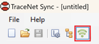
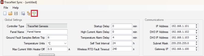
Network View:
In the network view, you can make global setting changes to the controller and configure the IP address of the HMI and DH3 gateway devices used for wireless RTD configurations.
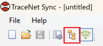
Hardware View:
The Hardware View must be configured before any circuits are configured in the Design View Page.
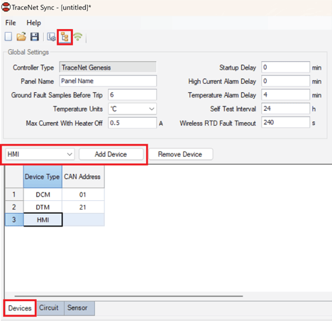
Devices Tab:
Select the devices from the dropdown menu and click "Add Device." At least one HMI, one DCM, and one DTM module are required in the panel configuration. No address is required for the HMI. Here, you can modify the CANBUS address of the devices.
Sensor Tab:
All of the available RTDs will be listed here. These are the RTD global settings and the RTD mode should be configured here. For example, if your panel has an ambient RTD, This RTD must be configured to the correct RTD Mode.
The available RTD modes are:
- Standard Control Mode – Control/Alarm/Trip
- Ambient - Control/Low Temp = DIS
- Monitor Mode 1 – Alarm/Trip
- Monitor Mode 2 – Trip
- Monitor Mode 3 – Alarm
- Monitor Mode 4 – Monitor Only
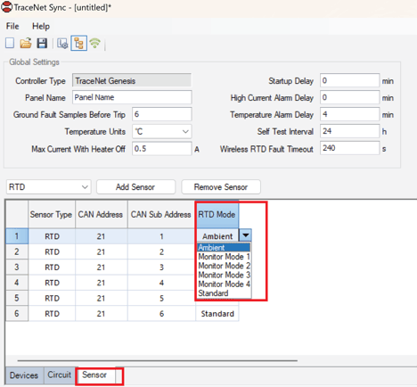
This must be configured here before RTD's are configured for each circuit.
Circuit Tab:
Lists all available circuits, which depend on how many DCM modules were added. Users can update the "Design Reference," intended to be the circuit tag, in this tab or the Designer View Section.
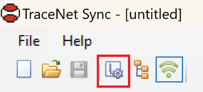
Designer View:
In this view is where all of the individual heat trace circuit configurations may be made. This article won’t go into the details of each setting parameter but will highlight a few key notes:
- Circuits that appear here are determined by the quantity of DCM modules that have been added. If you need to add more circuits you should add the appropriate amount of DCMs prior to this step.
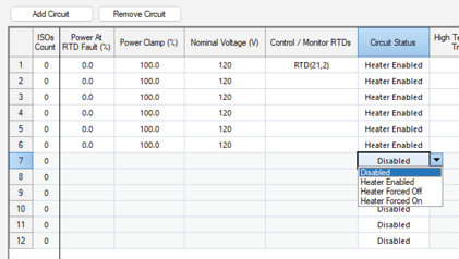
- If any rows are greyed out this is because the circuits are “Disabled”. Navigate to the “Circuit Status” column and select the correct status:
- Enabled
- Disabled
- Forced On
- Forced Off
- The table view of the Designer View acts similarly to Excel. Users can copy and paste information from excel sheets into multiple cells at one time.
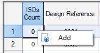
ISO Count Column:
Here users can right click on the ISO count and click “Add”. Here you attach related drawings to that circuit. You can also complete this activity in bulk See Adding Drawings In Bulk
Design reference Column:
This is primarily intended to be the heat trace circuit tag.
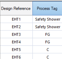
Process Tag Column:
Heat trace circuits may be grouped into categories using the same “Process Tag”. Alarms for these circuits are categorized in the Genesis HMI Alarm List
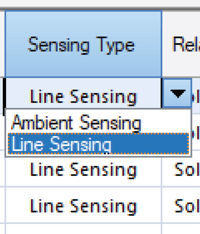
Sensing Type Column:
Used to select if the circuit is:
- Line Sensed
- Ambient Sensed
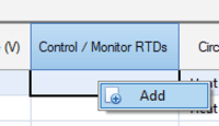
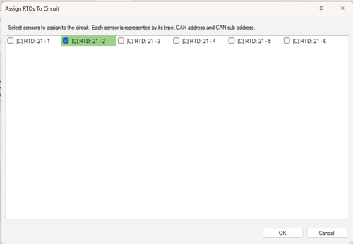
Control / Monitor RTDs Column:
Users can right click in the desired cell and assign the appropriate RTD to the circuit. A max of 20 RTD2 can be assigned to a single circuit A single RTD can be assigned to multiple circuits
Adding Drawings In Bulk:
To add drawings in bulk and assign them to heat trace circuits:
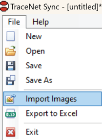
- Click on File and select Import Images.
- Click "Add ISO" and choose multiple drawings. The typical format for these drawings is PDF.
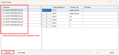
- The list of drawings will appear in the left window. Drag the drawings to the correct heat trace circuit. Multiple drawings can be assigned to a single circuit.
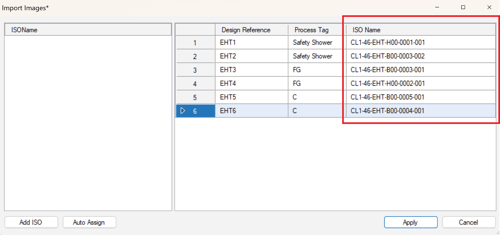
- Click Apply.
Save your Configuration File
Remember to save your file. This will be the file imported into the Genesis HMI.