
Legend:
Step 1. Confirm Failure and Prepare Replacement Parts
Step 2. Cable Preparation
Step 3. Joining Conductors
Step 4: Secure Barrel
Step 5: Fill Barrel
Step 6: Water Test
Step 7: Install Bell Mouth (Hot/Cold Splice Repairs Only)
Step 8: Final Test & Install
Appendix A: Drilling Stainless Steal
Appendix B: M.I. Splice Kit
Appendix C: Splice Repair Form
Appendix D: Cold Lead Information
Appendix E: Drill Bit Selection Guide
Appendix F: Insulation Resistance Testing (Meggering) – M.I Cables
Important Notes Before Starting Any Repair:
- Once any repair has started it must be finished to prevent moisture entering cable and possibly damaging entire cable beyond repair. Always schedule extra time for repair because of this.
- Repairs can only be completed if the cable is increased/decreased by a total of 3%. If more than 3% of the cable must be removed due to damage the trace cannot be completed. Ex. If cable overall length is 53M, 1.59M can be removed or added (53*.03=1.59)
- Continuous IR testing of the cable is recommended if possible.
- When replacing a cold lead, the same part is required for replacement. Different manufactures substitutes cannot be used. See Appendix D for cold lead part numbers and Pentair part number conversion table
- While soldering, it is important to avoid using excess heat on the portion to be soldered. Direct flame contact can oxidize the metal surface preventing the solder from adhering to the metal. Also, excess heat can cause the joined conductors to melt and separate.
- Before starting an EHT splice the EHT circuit must be locked out and verified for zero energy. This should be completed before troubleshooting
Tools Required:
- Propane Torch
- Tube Cutters
- Calipers
- Barrel
- Multimeter and Insulation Resistance Meter (IR Meter)
- File
- Wax stick
Step 1. Confirm Failure and Prepare Replacement Parts:
After the failure point has been identified the first step to completing the EHT splice is the confirming the failure point and prepare the replacement parts.
Tools Required:
- Propane Torch
- Tube Cutters
- Calipers
- Barrel
- Multimeter and Insulation Resistance Meter (IR Meter)
- File
- Wax stick
Steps: The following steps are completed at the cable failure point:
- Move the cable 150mm (6”) away from the surface
- Remove Bell Mouth for reuse (Hot/Cold splice repair only):
- Apply heat directly to bell mouth using a propane torch
- Use pliers or channel locks to remove
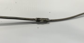
- Cut the damaged section of cable (or joint) using tube cutters
- Note: If removing joint cut at minimum 25mm from joint
- Note: If removing joint cut at minimum 25mm from joint
- Complete a continuity and IR test at both cut sections of trace to confirm failure point and no other failures exist.
- Ensure resistance value matches isometric.
- Record IR test results
- The result should be >20MΩ
- If another failure is found:
- Using propane torch, seal both exposed sections with wax stick
- Complete further troubleshooting to identify repair
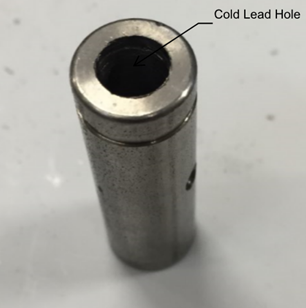
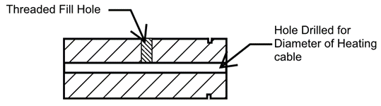
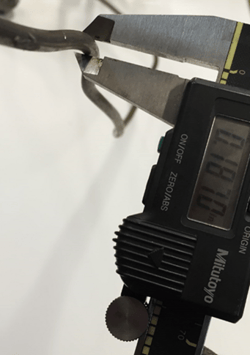
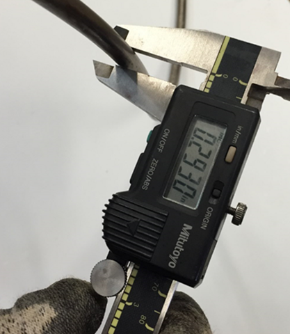
- Using calipers measure the outside diameter of the heat cable and cold lead (if required)
- Use Appendix E to select correct drill bit size(s)
- Two drill bit sizes are required for Hot/Cold splice repairs
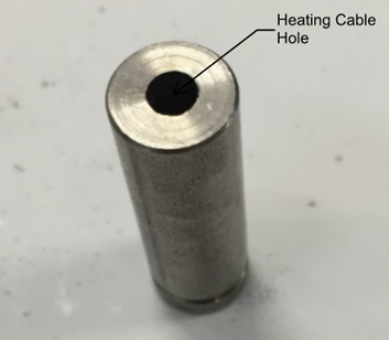
- Select the correct drill bit for the heat trace cable
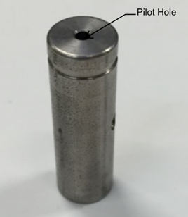
- Drill the barrel completely through the center of the pilot hole
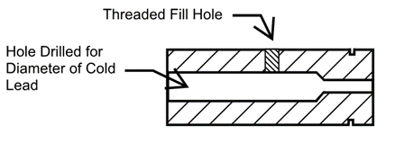
- Select the correct drill bit for the cold lead
- Mark drill bit approximately 25-30mm
- Drill the barrel through on one end approximately 25-30mm
- Clean barrel of any debris and smooth edges using file and emery cloth
- Verify Acetylene is in operating condition
- Before cutting the cables it is important to verify the torch is operating correctly, replace gas and clean tips as required
- Before cutting the cables it is important to verify the torch is operating correctly, replace gas and clean tips as required
Step 2. Cable Preparation
The next steps identify how to prepare the heating cable and cold lead for the splice.
Tools Required:
- Tube Cutters
- IR Meter
- File
- Splice Jig
- Side Cutters
- Sandpaper
- Pick Set
Steps: The following steps are completed at the cable failure point:
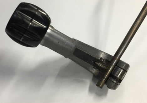
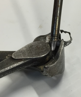
- Setup splice jig in suitable location and strap tightly to structure (typically pipe)
- Straighten the heating cable and cold lead a minimum of 300m (12”)
- Connect IR Meter to cable conductors
- Ensure value is >20MΩ
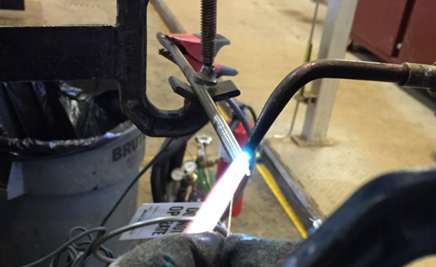
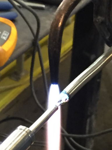
- If IR result is low use large flame on acetylene turbo torch to heat out moisture from cable. Start 300mm (12”) away from the cut cable and move forward to approximately 25mm (1”). Repeat several times. The process can take several minutes to complete.
- Test both cables
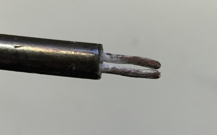
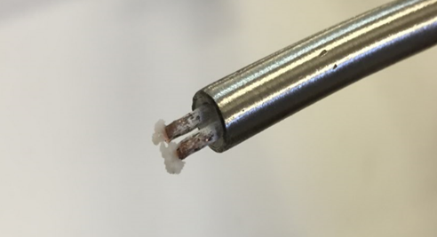
- Score both sections of cable (heat cable and cold lead) approximately 6mm to 13mm (¼” to ½”) with a tube cutter
- Score only do not completely cut cables through. Cutting through or too deeply forces the inner sheath to be pushed towards the conductors and may cause future failures.
- Score only do not completely cut cables through. Cutting through or too deeply forces the inner sheath to be pushed towards the conductors and may cause future failures.
- Grip the edge of the sheath with side cutters and twist clockwise to strip back the sheath. Pell back until score marking is reached.
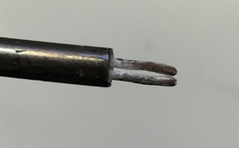
- Use a file to remove burrs from the sheath
- Use side cutters to cut ends of cable conductors
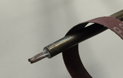
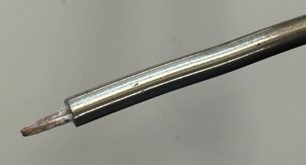
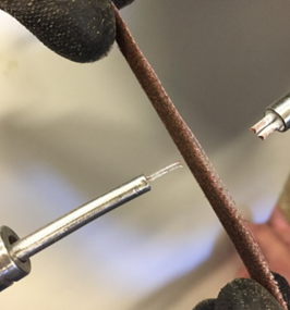
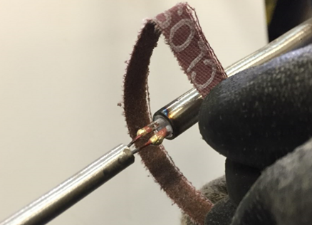
- Use sandpaper to clean conductors (this should be done gently with fine conductor heating cables)
- Clean circumference of conductors
- Clean ends of conductors
- Straighten conductors on both cables using pliers
- Conductor length should be approximately 6mm to 13mm (¼” to ½”)
- Use sandpaper to clean sheath approximately 100mm (4”) from end
- Use picks to remove any excess MgO between conductors
- Repeat with other cable
Step 3. Joining Conductors
After preparation is complete the next step is to join the conductors of the two cables. It is recommended that constant IR testing is completed for the duration of the splice.
Tools Required:
- Acetylene Turbo Torch
- IR Meter
- Silver Solder
- Splice Jig
- Pliers
- Gas Monitor
- Pick Set
- Bent Needle Nose Pliers
- Handy Flux (Black)
Steps:
- Slide the barrel and the bell mouth over the heating cable (For hot/cold splice repairs, slide overheating cable)
- Bellmouth only required for hot/cold splice repair. Ensure it is on outside barrel (ie. slide bell mouth on heating cable first then barrel)
- Place both cables into splice jib and tightly secure
- Ensure adequate distance between conductors
- Apply a small amount of flux using the pick to cold lead conductors (or one of the heating cables for hot/hot repair)
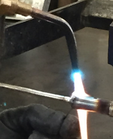
- Using Acetylene Turbo Torch lightly heat the flux on conductors
- Using Acetylene Turbo Torch place a small amount of solder onto both conductors (conductors with flux) – this is called tinning
- Ensure flux is only on the end of conductors and not near MgO
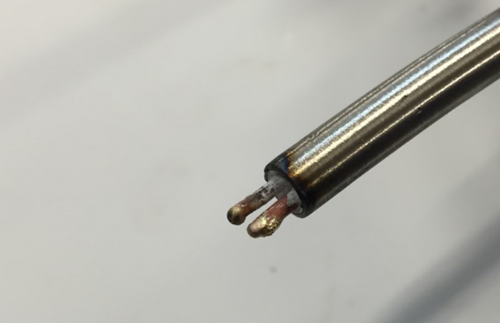
- Ensure flux is only on the end of conductors and not near MgO
- Loosen splice job and align cable conductors and ensure tips are touching
- Using a pick apply a small amount of flux to conductors
- Use Acetylene Turbo Torch and apply a low amount of heat to each conductor set individually
- Note that additional solder is not required to one set of conductors. Heating this up will provide a solidly connected joint.
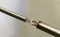
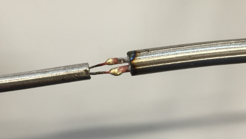
- Note that additional solder is not required to one set of conductors. Heating this up will provide a solidly connected joint.
- Use sandpaper to clean conductors and joint location
- Straighten conductors using needle nose pliers
- Confirm IR test reading is >20MΩ
- Moisture can enter the cable – ensure it removed at this time using the acetylene turbo torch.
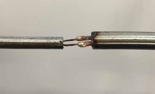
- Moisture can enter the cable – ensure it removed at this time using the acetylene turbo torch.
Step 4: Secure Barrel
After the cables are connected the next step is to attach the barrel to the conductors. It is recommended that constant IR testing is completed for the duration of the splice.
Tools Required:
- Acetylene Turbo Torch
- IR Meter
- Lrg Silver Solder
- Splice Jig
- Pliers
- Gas Monitor
- Pick Set
- Bent Needle Nose Pliers
- Brazing Flux (White)
Steps:
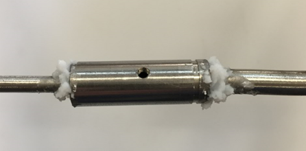
- Slide the barrel over the connected conductors.
- Face fill hole up
- Center fill hole over conductors
- Apply a large amount of flux to both sides of the barrel
- Use Acetylene Turbo Torch to heat barrel and melt flux
- At one side of the barrel apply a large amount of large solder to top of the area
- Solder will wick around the joint and draw solder from inside the joint to make a strong weld
- Use solder as required in the step
- Repeat this process for other side of the barrel
- Use sandpaper to clean barrel and sheath of both cables
- Visual inspect barrel ends for an opening in the solder
Step 5: Fill Barrel
After the barrel is soldered the barrel must be filled with MgO powder and completely sealed. This is the last time moisture can be removed from the cable. Verify IR test readings to ensure <20MΩ before starting step.
Tools Required:
- Acetylene Turbo Torch
- MgO
- IR Meter
- Silver Solder
- Brass Screw
- Pliers
- Gas Monitor
- Pick Set
- Bent Needle Nose Pliers
- Brazing Flux (White)
Steps:
- Using a syringe filled with MgO fill the fill hole of the barrel
- Gently tap sheath of the conductor with pliers while filling to ensure barrel is completely filled.
- Insert the brass screw into fill hole and turn 2-3 full turns (or until it breaks off)
- If the brass screw does not break cut with side cutters
- File screw so it is flush with the barrel
- Use the end of the barrel to file screw into the barrel
- Apply flux onto the brass screw
- Use Acetylene Turbo Torch to heat barrel and flux
- Apply solder to brass screw and fill in a depressed area
- Use sandpaper to clean barrel
Step 6: Water Test
After splicing is complete a water test must be completed. The water test will detect if any solider pinholes are present at sides or top of the barrel. It is important to continue IR testing throughout this step. If no fluctuations are present during the test and the IR is >20MΩ the cable has passed.
Tools Required:
- Bottle of water
- Cloth
- IR Meter
- Splice Repair Form
Steps:
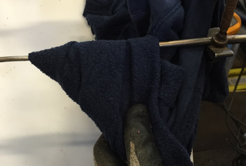
- Using one hand hold a cloth or rag under the barrel
- Using other hand pour water over barrel
- Wrap cloth in the barrel and leave applied for 2-4 minutes
- Continually monitor IR readings
- If no fluctuations are present during the test and the IR is >20MΩ the cable has passed.

- If no fluctuations are present during the test and the IR is >20MΩ the cable has passed.
Step 7: Install Bell Mouth (Hot/Cold Splice Repairs Only)
If required install bellmouth.
Tools Required:
- Loctite 262
Steps:
- Apply Loctite 262 to the edge of the barrel
- Slide over bell mouth and hold momentarily
Step 8: Final Test & Install
The area to be cleaned, tools removed, and cable reinstalled to the pipe. Final testing will also need to be completed and recorded.
Tools Required:
- IR Meter
Steps:
- Install MI cable to pipe
- Ensure cable is not bent within 150mm (6”) of barrel
- Complete resistance and IR test to the cable
- Verify resistance of cable matches EHT isometric and cable tag
- IR is >20MΩ
- Complete Splice Repair Form (Appendix C)
Appendix A
Drilling Stainless Steel
M.I splices require drilling of a stainless-steel alloy 825 barrel. Doing this incorrectly can lead to failed splices and broken drill bits. This is caused by excess heat – when stainless-steel heats up it becomes hard. This makes it difficult to drill, leading to broken bits and wasted barrels.
The material, spindle speed, feed and generated heat need to be considered when drilling barrels. Below is a list of do’s and don’ts when drilling barrels.
To-Do’s
Material: Use the proper tool for the job. Cobalt drill bits are recommended due to their hardness. They are harder than high-speed steel bits. The downside to this is they are more expensive and are more brittle. Following the remaining “to-do’s” will prolong drill bit life.
Control Speed: To reduce heat a steady feed speed is required – the larger the drill bit the slower the spindle speed. Recommended spindle speeds:
| Drill Size | Diameter (Inches) Required Speed (RPM) | Required Speed (RPM) |
| 1/16" | 0.0625 | 2445 |
| 1/8" | 0.125 | 1222 |
| 3/16" | 0.1875 | 815 |
| 1/4" | 0.25 | 611 |
| 5/16" | 0.3125 | 489 |
| 3/8" | 0.375 | 407 |
| 7/16" | 0.4375 | 349 |
Back Out: Build up of debris can lead to roughness and broken drill bits. Back out frequently.
Not-To-Do’s
Do Not Go to Fast: As drill speed increases more pressure is required. Without maintaining proper feed, the drill will create friction and heat
Cutting Oil: Cutting oil is not recommended when drilling barrels. It is difficult to remove contaminants from barrel even with cleaning agents. This can lead to failed splices.
Appendix B
M.I. Splice Kit
Calipers: Measure thickness of cold lead and heating cable outside diameter. Required to select correct drill bit size when drilling the barrel
Tube Cutter: Cut sheath of cold lead and heating cable
Files: Clean and smooth edges of heating cable and cold lead sheath. File down brass screw inserted in fill hole. Recommended files are 4” round, 8” flat, 8” half-round.
Large Diagonal Side Cutters: Cut cables, peel sheath and cut conductors
Small Diagonal Side Cutters: Cut/trim cable conductors
Bent Nose Pliers: Straighten and space conductors
Flint Striker: Ignite torch
Drill Bit Set: Drill barrel to correct size – cobalt drill bits are recommended
Loctite Adhesive: Secure Bell Mouth to barrel
Splice Jig: Clamp and support M.I. cables during splice
Metal Pick Set: Clean debris around conductors. Commonly used to apply flux
Propane Torch: Small torch used to troubleshoot M.I cable failures
Acetylene Turbo Torch: Solder conductors and barrel. Commonly used to troubleshoot M.I. cable failures
Torch Tip Cleaner: Clean torch tip
Multimeter and Insulation Resistance Meter (IR Meter): Troubleshoot and test cable
Emery Cloth: Clean cable conductors and sheath. Used to polish barrels after splice is completed.
Wax Stick: Preserve M.I cables and prevent excess moisture from penetrating MgO inside cables.
Magnesium Oxide (MgO): Insulation for M.I cables. Required to fill barrel completely during splice.
Silver Solder: Create a permanent bond between metal workpieces. Large size used for barrel to sheath connection, small size used for conductor connection.
Brazing Flux: Dissolve oxides on metal surfaces, and acts as heat transfer medium. Typically used for the barrel to the sheath and brass screw seal solder connections
Handy Flux: Dissolve oxides on metal surfaces, prevents oxidation and acts as heat transfer medium. Typically used for the conductor to conductor connections (lower temperature)
Brass Screw: Seals top of the barrel after MgO fills the barrel
Barrel: Houses/protects splice connection – different sizing for different cold lead and heating cables.
Appendix C
Splice Repair Form

Appendix D
Cold Lead Information
Thermon Cold Leads:
|
Cold Lead Size AWG (mm 2) |
Heater Sets A/D/E Current Rating (A) |
Gland Size |
Heater Set B Current Rating (A) |
Gland Size2 |
|
12 (3,3) |
20 |
M20 |
25 |
M20 |
|
10 (5,3) |
30 |
M25 |
40 |
M20 |
|
8 (8,4) |
45 |
M32 |
50 |
M25 |
Pentair Cold Leads:
|
Cable Design A,D,E |
|||||
|
Cold Lead Part Number |
Maximum Voltage (V) |
Maximum Current (A) |
Gland Size (NPT) |
Gland Size Reference |
Tail Size (AWG) |
|
S25A |
600 |
25 |
1/2" |
N12 |
14 |
|
LS23A |
300 |
23 |
1/2" |
N12 |
14 |
|
S34A |
600 |
34 |
3/4" |
N34 |
10 |
|
S49A |
600 |
49 |
3/4" |
N34 |
8 |
|
S65A |
600 |
65 |
3/4" |
N34 |
6 |
|
Cable Design B |
|||||
|
Cold Lead Part Number |
Maximum Voltage (V) |
Maximum Current (A) |
Gland Size (NPT) |
Gland Size Reference |
Tail Size (AWG) |
|
S29A |
600 |
29 |
1/2" |
N12 |
12 |
|
S40A |
600 |
40 |
1/2" |
N12 |
10 |
|
S48A |
600 |
48 |
1/2" |
N12 |
8 |
|
S66A |
600 |
66 |
1/2" |
N12 |
6 |
|
S86A |
600 |
86 |
1/2" |
N12 |
4 |
Pentair Cold Lead Conversion:
Updated part numbers for replacing older Alloy 825 two conductor Pentair cold leads.
|
Old Cold Lead Part Number |
Old Cold Lead Part Number |
||
|
Part Number |
Maximum Current |
Part Number |
Maximum Current |
|
14NS |
15 |
S25A |
25 |
|
12LS |
20 |
LS23A |
23 |
|
12NS |
20 |
S34A |
34 |
|
10NS |
30 |
S49A |
49 |
|
8NS |
50 |
S65A |
65 |
Appendix E
Drill Bit Selection Guide
|
Cable Diameter Imperial (in) |
Drill Identifier |
Cable Diameter Metric (mm) |
Drill Identifier |
Cable Diameter Imperial (in) Cont'd |
Drill Identifier |
Cable Diameter Metric (mm) Cont'd |
Drill Identifier |
|
0.124 - 0.131 |
30 |
3.1496 - 3.3274 |
30 |
0.262 - 0.263 |
H |
6.6548 - 6.6802 |
H |
|
0.132 - 0.135 |
29 |
3.3528 - 3.429 |
29 |
0.264 - 0.267 |
6.8mm |
6.7056 - 6.7818 |
6.8mm |
|
0.136 - 0.139 |
28 |
3.4544 - 3.5306 |
28 |
0.268 - 0.272 |
I |
6.8072 - 6.9088 |
I |
|
0.14 - 0.142 |
27 |
3.556 - 3.6068 |
27 |
0.273 - 0.276 |
J |
6.9342 - 7.0104 |
J |
|
0.143 - 0.144 |
26 |
3.6322 - 3.6576 |
26 |
0.277 - 0.28 |
K |
7.0358 - 7.112 |
K |
|
0.145 - 0.147 |
25 |
3.683 - 3.7338 |
25 |
0.281 - 0.285 |
7.25mm |
7.1374 - 7.239 |
7.25mm |
|
0.148 - 149 |
24 |
3.7592 - 3784.6 |
24 |
0.286 - 0.29 |
L |
7.2644 - 7.366 |
L |
|
0.15 - 0.151 |
23 |
3.81 - 3.8354 |
23 |
0.291 - 0.292 |
M |
7.3914 - 7.4168 |
M |
|
0.152 |
5/32 |
3.8608 |
5/32 |
0.293 - 0.297 |
19/64 |
7.4422 - 7.5438 |
19/64 |
|
0.153 - 0.154 |
22 |
3.8862 - 3.9116 |
22 |
0.298 - 0.302 |
N |
7.5692 - 7.6708 |
N |
|
0.155 - 0.158 |
21 |
3.937 - 4.0132 |
21 |
0.303 - 0.307 |
7.8mm |
7.6962 - 7.7978 |
7.8mm |
|
0.159 - 0.161 |
20 |
4.0386 - 4.0894 |
20 |
0.308 - 0.311 |
42506 |
7.8232 - 7.8994 |
42506 |
|
0.162 - 0.164 |
19 |
4.1148 - 4.1656 |
19 |
0.312 - 0.314 |
0 |
7.9248 - 7.9756 |
0 |
|
0.165 - 0.167 |
18 |
4.191 - 4.2418 |
18 |
0.315 - 0.318 |
8.1mm |
8.001 - 8.0772 |
8.1mm |
|
0.168 |
11/64 |
4.2672 |
11/64 |
0.319 - 0.323 |
p |
8.1026 - 8.2042 |
p |
|
0.169 - 0.172 |
17 |
4.2926 - 4.3688 |
17 |
0.324 - 0.327 |
21/64 |
8.2296 - 8.3058 |
21/64 |
|
0.173 - 0.175 |
16 |
4.3942 - 4.445 |
16 |
0.328 - 0.334 |
Q |
8.3312 - 8.4836 |
Q |
|
0.176 - 0.177 |
15 |
4.4704 - 4.4958 |
15 |
0.335 - 0.339 |
R |
8.509 - 8.6106 |
R |
|
0.178 - 0.18 |
14 |
4.5212 - 4.572 |
14 |
0.34 |
11/32 |
8.636 |
11/32 |
|
0.181 - 0.182 |
13 |
4.5974 - 4.6228 |
13 |
0.341 - 0.343 |
8.5mm |
8.6614 - 8.7122 |
8.5mm |
|
0.183 - 0.184 |
3./16 |
4.6482 - 4.6736 |
3./16 |
0.344 - 0.349 |
S |
8.7376 - 8.8646 |
S |
|
0.185 - 0.186 |
12 |
4.699 - 4.7244 |
12 |
0.35 - 0.353 |
9.0mm |
8.89 - 8.9662 |
9.0mm |
|
0.187 - 0.188 |
11 |
4.7498 - 4.7752 |
11 |
0.354 |
T |
8.9916 |
T |
|
0.189 - 0.191 |
10 |
4.8006 - 4.8514 |
10 |
0.355 - 0.359 |
23/64 |
9.017 - 9.1186 |
23/64 |
|
0.192 - 0.194 |
9 |
4.8768 - 4.9276 |
9 |
0.36 - 0.363 |
9.25mm |
9.144 - 9.2202 |
9.25mm |
|
0.195 - 0.196 |
8 |
4.953 - 4.9784 |
8 |
0.364-0.37 |
U |
9.2456 - 9.398 |
U |
|
0.197-0.198 |
7 |
5.0038 - 5.0292 |
7 |
0.371-0.372 |
3./8 |
9.4234 - 9.4488 |
3./8 |
|
0.199 |
13/64 |
5.0546 |
13/64 |
0.373-0.377 |
V |
9.4742 - 9.5758 |
V |
|
0.2 |
6 |
5.08 |
6 |
0.378-0.381 |
9.7mm |
9.6012 - 9.6774 |
9.7mm |
|
0.201-0.204 |
5 |
5.1054 - 5.1816 |
5 |
0.382-0.385 |
W |
9.7028 - 9.779 |
W |
|
0.205-0.208 |
4 |
5.207 - 5.2832 |
4 |
0.386 - 0.389 |
25/64 |
9.8044 - 9.8806 |
25/64 |
|
0.209 - 0.214 |
3 |
5.3086 - 5.4356 |
3 |
0.39 - 0.392 |
10.0mm |
9.906 - 9.9568 |
10.0mm |
|
0.215 - 0.216 |
7/32 |
5.461 - 5.4864 |
7/32 |
0.393 - 0.399 |
X |
9.9822 - 10.1346 |
X |
|
0.217 - 0.219 |
2 |
5.5118 - 5.5626 |
2 |
0.4 - 0.401 |
Y |
10.16 - 10.1854 |
Y |
|
0.22 - 0.223 |
5.7mm |
5.588 - 5.6642 |
5.7mm |
0.402 - 0.408 |
13/32 |
10.2108 - 10.3632 |
13/32 |
|
0.224 - 0.227 |
1 |
5.6896 - 5.7658 |
1 |
0.409 - 0.417 |
Z |
10.3886 - 10.5918 |
Z |
|
0.228 - 0.229 |
5.9mm |
5.7912 - 5.8166 |
5.9mm |
0.418 - 0.432 |
27/64 |
10.6172 - 10.9728 |
27/64 |
|
0.23 - 0.233 |
A |
5.842 - 5.9182 |
A |
0.433 - 0.448 |
7./16 |
10.9982 - 11.3792 |
7./16 |
|
0.234 - 0.237 |
B |
5.9436 - 6.0198 |
B |
0.449 - 0.464 |
29/64 |
11.4046 - 11.7856 |
29/64 |
|
0.238 - 0.241 |
c |
6.0452 - 6.1214 |
c |
0.465 - 0.479 |
15/32 |
11.811 - 12.1666 |
15/32 |
|
0.242 - 0.245 |
D |
6.1468 - 6.223 |
D |
0.48 - 0.495 |
31/64 |
12.192 - 12.573 |
31/64 |
|
0.246 - 0.247 |
1./4 |
6.2484 - 6.2738 |
1./4 |
0.496 - 0.542 |
1./2 |
12.5984 - 13.7668 |
1./2 |
|
0.248 - 0.252 |
6.4mm |
6.2992 - 6.4008 |
6.4mm |
0.543 - 0.62 |
35/64 |
13.7922 - 15.748 |
35/64 |
|
0.253 - 0.256 |
F |
6.4262 - 6.5024 |
F |
0.621 - 0.635 |
5./8 |
15.7734 - 16.129 |
5./8 |
|
0.257 - 0.26 |
G |
6.5278 - 6.604 |
G |
0.636 |
41/64 |
16.1544 |
41/64 |
|
0.261 |
17/64 |
6.6294 |
17/64 |
Appendix F: Insulation Resistance Testing (Meggering) – M.I Cables
Properly conducting insulation resistance testing is important to properly test any EHT cable. The test measures the resistance (in MOhms) from the cable conductors to the cable sheath. The test used high DC voltage (500VDC or 1000VDC), the higher voltage is required to provide the voltage potential to detect any failures.
This test will be able to determine:
- Any faults in EHT cable
- Moisture presence in the MgO powder
- Any leaks to ground
Procedure
- Ensure the EHT circuit is isolated and locked out
- Ensure the power terminations have been removed from the EHT controller or junction box.
- This removes the potential of accidentally inducing a high voltage into components of the EHT control panel.
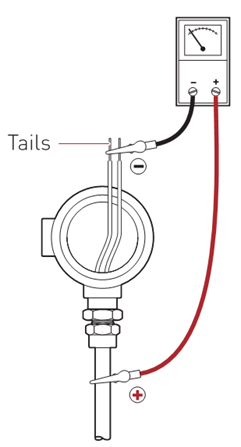
- Place the negative test lead to the conductor(s)
- Using both conductors is a standard test
- Testing individual conductors allows you to test if there is an open circuit
- Clamp the positive test lead to the sheath of the M.I. cable
- Select the appropriate test voltage on the insulation resistance meter
- 500VDC for 300V rated MI cable
- 1000VDC for 600V rated MI cable
- Turn the meter ON and apply the voltage for a minimum of 1 minute
Notes:
- In general, the higher the resistance the better insulation between the conductors and the sheath.
- Ideally, the insulation resistance reading should be infinitive (550+ or 2200+ on the Fluke 1587 meters)
- A passing megger is anything above 20Mohm
- When repairing a new cable during construction a passing megger is anything above 100Mohms