Introduction:
Welcome to the Electrical Heat Trace Installation Procedure, a comprehensive guide developed by Electrical Heat Trace Group Ltd. (EHT Group) to ensure the correct installation of electrical heat trace (EHT) and its components. The primary objective of this procedure is to safeguard process equipment and piping by implementing best practices for EHT installation. While this procedure serves as a general guide, it is essential to note that it does not replace existing customer standards. Instead, it provides a framework for executing EHT installations effectively and in accordance with industry best practices. Let's delve into the details of this procedure to ensure the successful deployment of your electrical heat trace systems.
Legend:
-
Flange Install: Steps for installing EHT components on flanges.
-
Valve Install: Guidelines for installing EHT components on valves.
-
Pipe Elbow Install: Procedures for installing EHT components on pipe elbows.
-
Dead Leg Install: Guidelines for installing EHT components on dead legs.
-
Pipe Shoe Install: Steps for installing EHT components on pipe shoes.
-
Dummy Leg Install: Procedures for installing EHT components on dummy legs.
-
Angle Pipe Support Install: Guidelines for installing EHT components on angle pipe supports.
-
Pressure Indicator Install: Steps for installing pressure indicators with EHT components.
-
Centrifugal Pump Install: Procedures for installing EHT components on centrifugal pumps.
-
Sight Glass Install: Guidelines for installing EHT components on sight glasses.
-
Magnetic Level Gauge Install: Steps for installing EHT components on magnetic level gauges.
-
Level Transmitter Install: Procedures for installing EHT components on level transmitters.
-
In-Line Strainer Install: Guidelines for installing EHT components on in-line strainers.
-
Steam Trap Install: Steps for installing EHT components on steam traps.
-
Relief Valve Install: Procedures for installing EHT components on relief valves.
-
Root Valve Install: Guidelines for installing EHT components on root valves.
-
Wall Penetration Install: Steps for installing EHT components on wall penetrations.
-
RTD Pipe Install: Procedures for installing RTD sensors on pipes.
-
RTD Tube Bundle Install: Guidelines for installing RTD sensors in tube bundles.
-
Quick Connectors Install: Steps for installing quick connectors for EHT components.
-
SR End Seal Connection Install: Steps for installing end seal connections for SR cables.
-
SR Tee Connection Install: Procedures for installing tee connections for SR cables.
EHT Adder Table:
The following table outlines the additional heat output requirements for piping system equipment. This chart serves as a reference when no customer standard is available.
Notes:
- ADDER IS DEFINED AS THE AMOUNT OF TRACING (IN LENGTH)
REQUIRED IN ADDITION TO THE EQUIPMENT LINEAR LENGTH. - IN CASES WHERE ADDERS ON THE EHT ISOMETRIC DIFFER
FROM THE ADDERS INDICATED IN THIS DRAWING, THE EHT
ISOMETRIC SHALL GOVERN. - REFER TO EHT ISOMETRIC FOR PUMP ADDERS GREATER THAN
12" NPS. - FOR PUMPS THE NPS REFERS TO THE SUCTION SIDE LINE
SIZE. - ONLY USE TYPICAL PIPE SUPPORT ADDERS WHEN THE PIPE
SHOE LENGTH IS NOT KNOWN. OTHERWISE USE PIPE SHOE
LENGTH TABLE TO GET THE ADDER LENGTH.
| STANDARD ADDER CHART (IN METERS) 1 of 2 | |||||||
| NPS | FLANGED 150 Valve | SCRD/SW/BW150 Valve | FLANGED 300 Valve | SCRD/SW/BW300 Valve | FLANGED 600/900 Valve | SCRD/SW/BW600/900 Valve | FLANGED 1500 Valve |
| 0.5" | 0.30 | 0.30 | 0.30 | 0.30 | 0.3 | 0.46 | 0.76 |
| 0.75" | 0.46 | 0.30 | 0.46 | 0.30 | 0.61 | 0.46 | 1.07 |
| 1" | 0.61 | 0.30 | 0.61 | 0.30 | 0.91 | 0.46 | 1.52 |
| 1.5" | 0.76 | 0.46 | 0.91 | 0.46 | 1.22 | 0.76 | 1.68 |
| 2" | 0.76 | 0.61 | 1.07 | 0.61 | 1.22 | 0.91 | 1.83 |
| 3" | 0.91 | 0.76 | 1.22 | 0.76 | 1.52 | 1.22 | 2.13 |
| 4" | 1.22 | 0.91 | 1.52 | 0.91 | 2.13 | 1.52 | 3.05 |
| 6" | 1.52 | 1.07 | 1.83 | 1.07 | 2.74 | 1.83 | 3.66 |
| 8" | 2.13 | 1.22 | 2.44 | 1.22 | 3.66 | 2.13 | 5.18 |
| 10" | 2.44 | 1.52 | 3.05 | 1.52 | 4.27 | 2.59 | 5.79 |
| 12" | 2.74 | 1.83 | 3.66 | 1.83 | 5.18 | 3.05 | 6.71 |
| 14" | 3.05 | 2.13 | 4.27 | 2.13 | 5.79 | 3.66 | 7.32 |
| 16" | 3.35 | 2.44 | 4.88 | 2.44 | 6.4 | 4.27 | 7.92 |
| 18" | 3.66 | 2.74 | 5.49 | 2.74 | 7.01 | 4.88 | 8.84 |
| 20" | 3.96 | 3.05 | 6.10 | 3.05 | 7.62 | 5.49 | 9.45 |
| 24" | 4.57 | 3.66 | 7.32 | 3.66 | 9.14 | 6.71 | 10.97 |
| 30" | 5.49 | N/A | 8.84 | N/A | 10.97 | N/A | 13.11 |
| 36" | 6.4 | N/A | 10.36 | N/A | 12.8 | N/A | 15.24 |
| 42" | 7.32 | N/A | 11.58 | N/A | 14.63 | N/A | 17.68 |
| 48" | 8.23 | N/A | 13.11 | N/A | 16.46 | N/A | 19.81 |
| 54" | 9.45 | N/A | 14.94 | N/A | 18.59 | N/A | 22.25 |
| 60" | 10.36 | N/A | 16.46 | N/A | 20.73 | N/A | 24.69 |
| 66" | 11.28 | N/A | 17.98 | N/A | 22.56 | N/A | 27.13 |
| 72" | 12.5 | N/A | 19.81 | N/A | 24.69 | N/A | 29.26 |
| STANDARD ADDER CHART (IN METERS) 2 of 2 |
|||||||
| NPS | SCRD/SW/BW1500 Valve | TYPICAL Pipe Support (Note 7) | ANGLE IRON PipeSupport | FLANGE PAIR | PUMP (Note 6) | VENTS | DRAINS |
| 0.5" | 0.61 | 0.91 | 0.3 | 0.3 | 1.52 | 0.15 | 0.15 |
| 0.75" | 0.61 | 0.91 | 0.3 | 0.3 | 1.52 | 0.30 | 0.30 |
| 1" | 0.61 | 0.91 | 0.46 | 0.46 | 1.52 | 0.30 | 0.30 |
| 1.5" | 1.07 | 0.91 | 0.46 | 0.46 | 1.52 | 0.30 | 0.30 |
| 2" | 1.52 | 0.91 | 0.46 | 0.46 | 3.05 | 0.30 | 0.30 |
| 3" | 1.83 | 0.91 | 0.61 | 0.61 | 4.57 | 0.30 | 0.30 |
| 4" | 2.13 | 0.91 | N/A | 0.61 | 6.10 | 0.30 | 0.30 |
| 6" | 2.44 | 0.91 | N/A | 0.61 | 7.62 | 0.60 | 0.60 |
| 8" | 3.05 | 0.91 | N/A | 0.61 | 7.62 | 0.60 | 0.60 |
| 10" | 3.66 | N/A | N/A | 0.91 | 9.14 | 0.60 | 0.60 |
| 12" | 4.27 | N/A | N/A | 1.07 | 10.67 | 0.60 | 0.60 |
| 14" | 5.18 | N/A | N/A | 1.22 | (Note 5) | 0.60 | 0.60 |
| 16" | 5.79 | N/A | N/A | 1.37 | (Note 5) | 0.60 | 0.60 |
| 18" | 6.71 | N/A | N/A | 1.68 | (Note 5) | 0.60 | 0.60 |
| 20" | 7.32 | N/A | N/A | 1.83 | (Note 5) | 0.70 | 0.70 |
| 24" | 8.84 | N/A | N/A | 2.13 | (Note 5) | 0.70 | 0.70 |
| 30" | N/A | N/A | N/A | 2.74 | (Note 5) | 0.70 | 0.70 |
| 36" | N/A | N/A | N/A | 3.35 | (Note 5) | 0.70 | 0.70 |
| 42" | N/A | N/A | N/A | 3.96 | (Note 5) | 0.70 | 0.70 |
| 48" | N/A | N/A | N/A | 4.57 | (Note 5) | 0.70 | 0.70 |
| 54" | N/A | N/A | N/A | 5.18 | (Note 5) | 0.70 | 0.70 |
| 60" | N/A | N/A | N/A | 5.79 | (Note 5) | 0.70 | 0.70 |
| 66" | N/A | N/A | N/A | 6.4 | (Note 5) | 0.70 | 0.70 |
| 72" | N/A | N/A | N/A | 7.01 | (Note 5) | 0.70 | 0.70 |
| PIPE Shoes | |
| Shoe Length | Adder (in meters) |
| 12” | 0.91 |
| 18” | 1.37 |
| 24” | 1.83 |
| 36” | 2.44 |
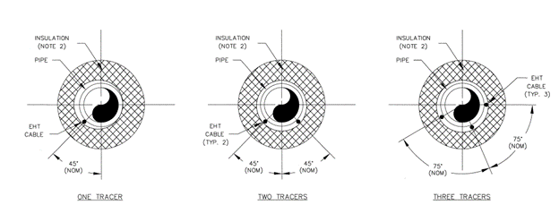
Pipe Orientation:
Below are the general installation methods for proper pipe orientation. (Image)
Minimum Bend Radius:
For SR Cable:

|

|
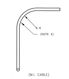
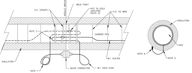
For MI Cable:
The minimum bend radius for MI cables should not be less than 3 times the outside diameter of the cable. Avoid reshaping or straightening MI cables with a bending radius less than six times its outside diameter. MI cables should not cross or overlap and should be a minimum of 25mm apart if possible.
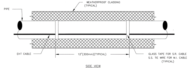
MI Cable Pipe Install:
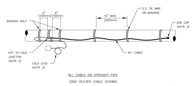
Procedure:
- Install the MI cable as per the EHT Isometric.
- Secure one end of the MI Cable to the pipe as per the EHT Isometric.
- Roll out the cable onto the pipe, loosely securing the cable along the way.
- Evenly distribute any MI cable length overages along the entire pipe length by waving the cable.
- Tighten tie wire.
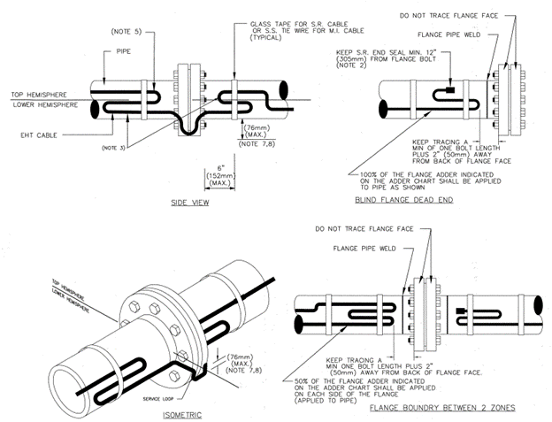
Flange Install:
For pipes with multiple passes of EHT cable, apply the full flange pair adder for each pass of EHT cable on each flange pair. In cases where it's physically impossible to install all required cable on the flange pair, utilize the remaining cable on the pipe to either side of the flange pair. Ensure a service loop of 50mm to 76mm is formed on the flange face to allow servicing of equipment. The EHT cable should cross over the flange in the lower hemisphere.
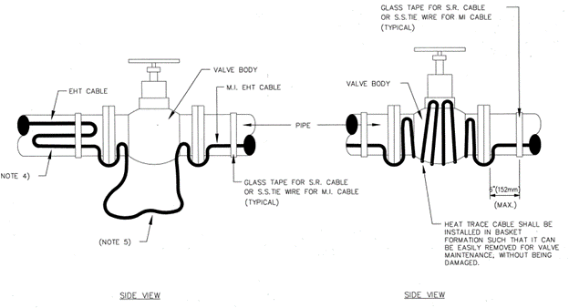
Valve Install:
Apply the full valve adder for each pass of EHT cable on the valve, for pipes with multiple passes of EHT cable.
Pipe Elbow Install:
Refer to the images provided for general installation methods.

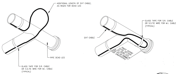
Dead Leg Install:
Refer to the images provided for general installation methods. Note that this does not apply to dummy leg supports.
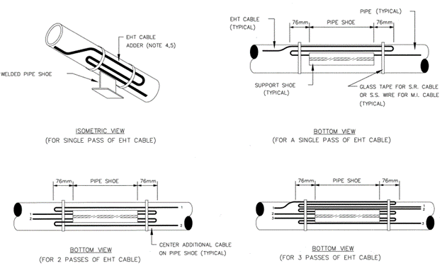
Pipe Shoe Install:
Refer to the images provided for general installation methods. Apply the full pipe shoe adder for each pass of EHT cable, and note that the adder does not include pipe shoe length.
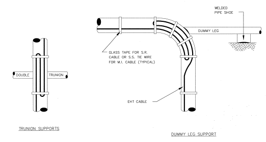
Dummy Leg Install:
Refer to the images provided for general installation methods. Apply the full dummy leg adder for each pass of EHT cable.
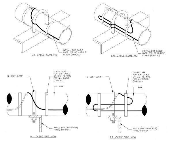
Angle Pipe Support Install:
Refer to the images provided for general installation methods.
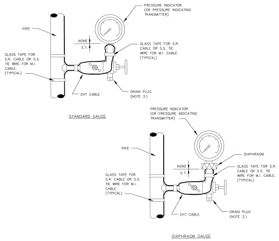
Pressure Indicator Install:
Refer to the images provided for general installation methods. Ensure that tracing is not installed over the drain plug.
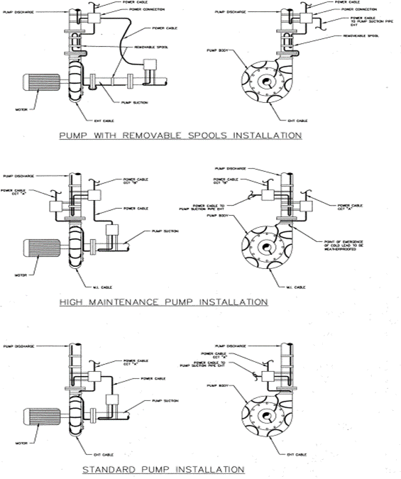
Centrifugal Pump Install:
Refer to the images provided for general installation methods. Cover the EHT cable with aluminum tape or metal foil before insulation is applied. Do not install EHT cable over the impeller access plate to allow for the removal of the impeller without tracing removal.
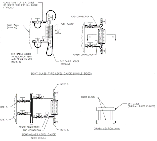
Sight Glass Install:
Refer to the images provided for general installation methods. Use aluminum tape or metal foil in the bolt area to aid in heat transfer. Ensure that the EHT cable is not installed over the plug of the drain or vent valve, and extend the cable to the vessel/tank wall.
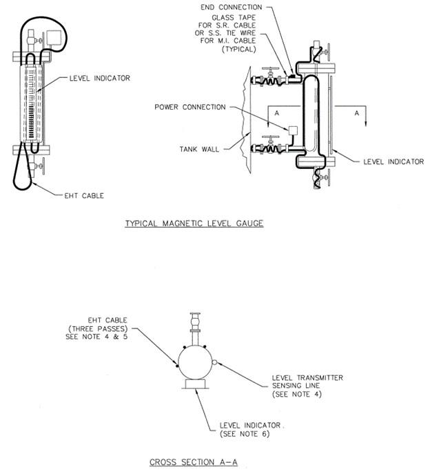
Magnetic Level Gauge Install:
Refer to the images provided for general installation methods. Ensure that the EHT cable does not come in contact with the level indicator or the level transmitter mounting straps. Additionally, make sure that the cable is not installed under the level indicator or level transmitter mounting straps. Avoid installing the cable over the plug of the drain or vent valve, and extend the cable to the vessel/tank wall.
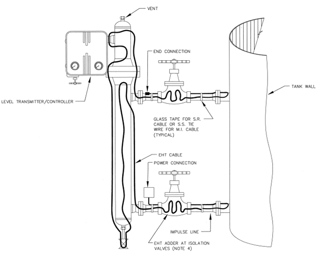
Level Transmitter Install:
Refer to the images provided for general installation methods.
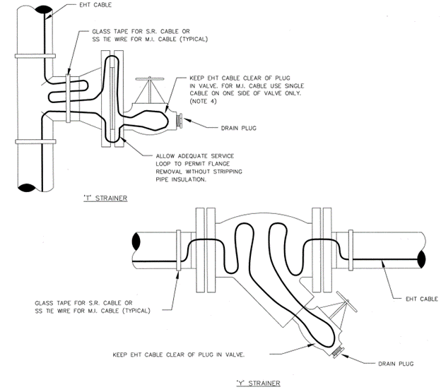
In-Line Strainer Install:
Refer to the images provided for general installation methods. Note that the strainer EHT cable adder will be identical to valve adders.
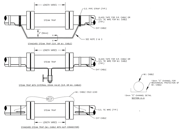
Steam Trap Install:
Refer to the images provided for general installation methods. Maintain a 50mm separation between the EHT cable and the steam trap.
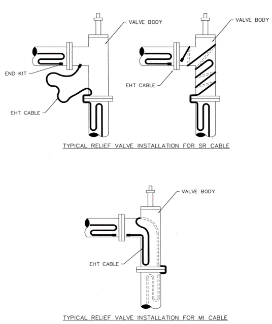
Relief Valve Install:
Refer to the images provided for general installation methods. For pipes with multiple passes of EHT cable, apply the relief valve leg adder for each pass of EHT cable. Ensure that the relief valve spring chamber is not traced.
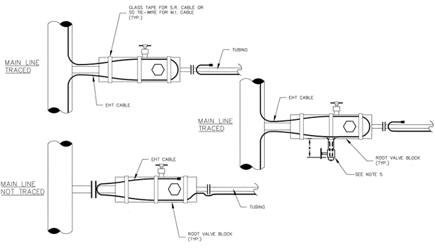
Root Valve Install:
Refer to the images provided for general installation methods. This applies to all root valves with EHT, regardless of service. The entire root valve block should be traced, while root valve branches need not be traced provided the length of the branch does not exceed 76mm.
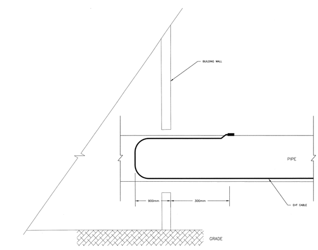
Wall Penetration Install:
Refer to the images provided for general installation methods. Ensure that the EHT cable continues for at least 900mm inside the building and ends at least 300mm outside of the building.
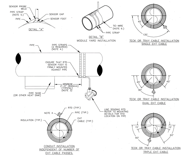
RTD Pipe Install:
Refer to the images provided for general installation methods. The RTD sensor should be placed a minimum of 90° from the nearest EHT cable or centred between two cables equally. RTDs shall be placed not less than 900mm from any heat sink (e.g., valve), excluding pipe shoes where the minimum distance shall be 600mm.
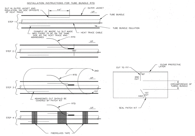
RTD Tube Bundle Install:
Refer to the images provided for general installation methods. Probe-style RTD must be used, and a 100mm slit in the outer jacket and insulation should be made just below where the RTD will be located.
Quick Connectors Install:
Refer to the images provided for general installation methods. Neatly coil excess cold lead, and ensure the looping back of the lead is more important than the coil.
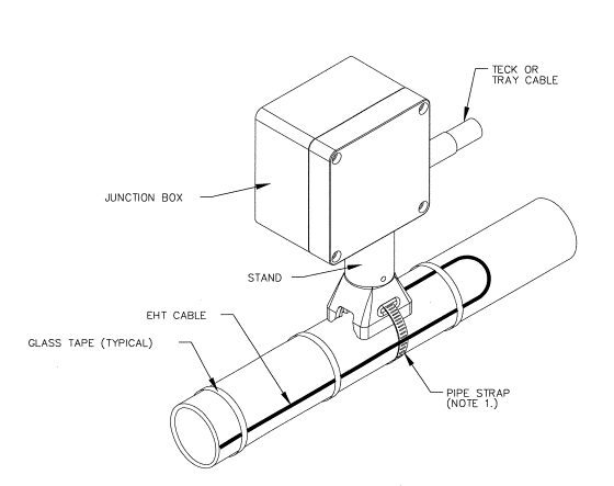
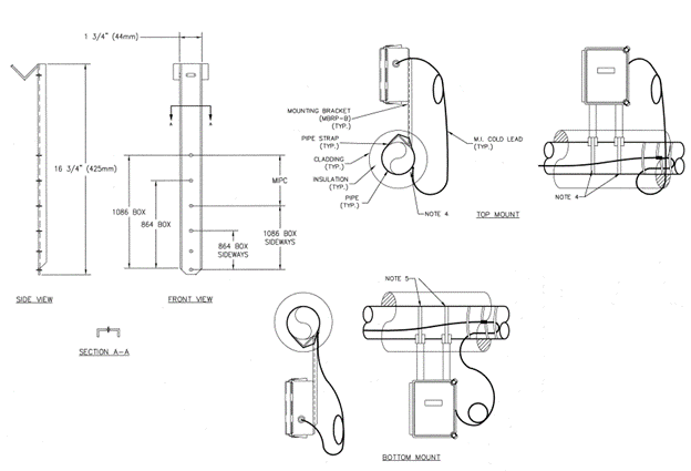
MI JB Mounting Bracket for Pipe Install:
Refer to the images provided for general installation methods. Route pipe straps under EHT cable.
SR Multi-Entry Power/Splice Connection Install:
Refer to the images provided for general installation methods. Ensure the sequence of installation is followed meticulously for proper connection and termination.
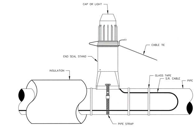
SR End Seal Connection Install:
Refer to the images provided for general installation methods. Ensure that the end seal is fastened to the top of the pipe with a strap without pinching the EHT cable.
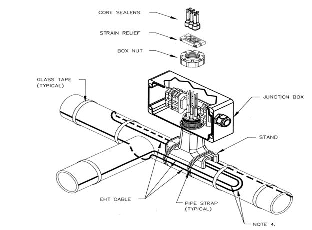
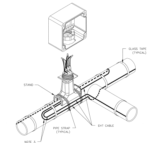
SR Tee Connection Install:
Refer to the images provided for general installation methods. Install the box on the top horizontal section of the pipe if available, and loop and tape 600mm of EHT cable to the pipe.
SR Single Entry Power Connection Install:
Refer to the images provided for general installation methods. Install the box on the top horizontal section of the pipe if available, and loop and tape 600mm of EHT cable to the pipe.