
Introduction:
Welcome to this guide on programming the Phoenix Contact GW Modbus device. If you're working in industrial automation and need to bridge the gap between Modbus RTU/ASCII and Modbus TCP, this device is your go-to solution. In this article, we'll provide clear and concise instructions on setting up the Phoenix Contact GW Modbus device, including configuring its IP address and serial communication settings. Whether you're a seasoned pro or just getting started, this guide will help you make the most of this powerful protocol converter. Let's get started!
How to Ping an IP Address using Command Prompt
-
Open Command Prompt: Press
Win + R, type "cmd," and press Enter to open the Command Prompt. -
Ping Command Syntax: To use "ping," type the following in Command Prompt:
css -
ping [IP Address or Hostname]Replace
[IP Address or Hostname]with the actual IP address or hostname of your device. -
Execute the Ping Command: Press Enter to execute the command.
-
Interpreting the Results: The "ping" command will send several packets to the specified IP address or hostname and wait for a response. You'll see statistics showing the number of packets sent, received, lost, and the round-trip time. If you receive replies from the device, it confirms successful communication.
-
Terminating the Command: To stop the continuous ping, press
Ctrl + C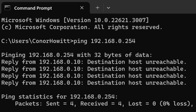
Phoenix Contact GW Modbus Default IP Address
The default network settings of the GWMODBUSTCP/RTU... are:
- IP address: 192.168.254.254
- Subnet mask: 255.255.255.0
- Gateway: 0.0.0.0
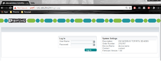
How to Login and Password
Open a web browser and enter the IP address of the GWMODBUSTCP/RTU... in the
“Address” field (default = 192.168.254.254).
- User name: Admin
- Default password: admin
Ensure your computer is on the same subnet as the device's IP address. You can watch the video above for a step-by-step guide.
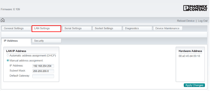
LAN Settings Page
-
This section is where you configure your device's IP address.
-
Typically, you'll select manual address assignment and input the new IP address and default gateway.
If you change your device's IP address, you may also need to adjust your laptop's IP address to be on the same subdomain as the new assignment.
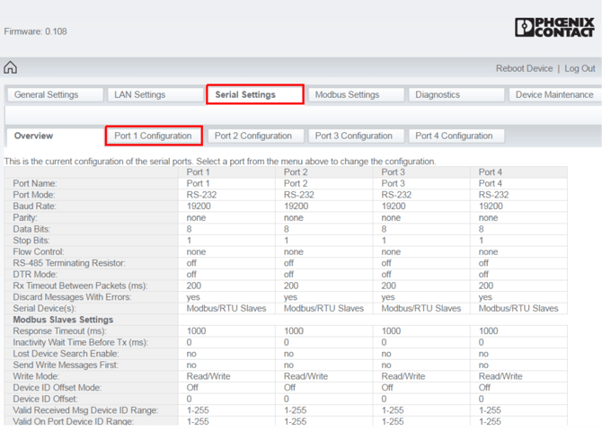
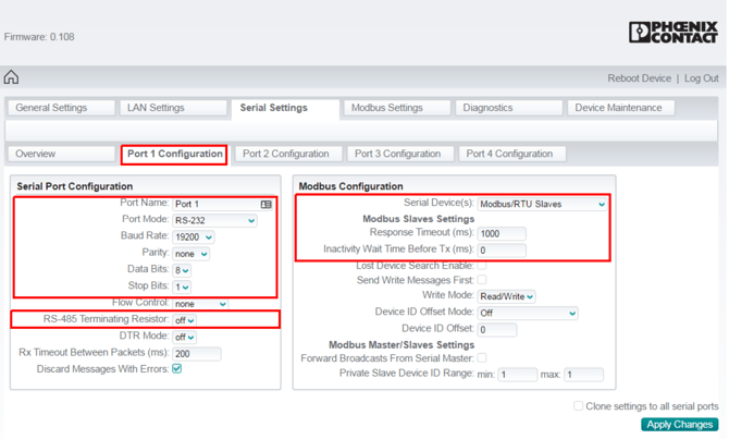
Serial Settings
Here you will select which serial port you want to configure. In each port:
-
Port Mode: Usually set to RS-485-2Wire.
-
Baud Rate / Parity / Data Bits / Stop Bits: These settings should match the configuration of the heat trace controllers you're connecting to.
-
RS-485 Resistor: Typically, it's turned on.
-
Serial Device: Choose between Modbus RTU Slave or Modbus ASCII Slave, depending on your setup.
-
Response Timeout: This setting determines the message timeout length and is typically set between 1000-3000 milliseconds.
-
Inactivity Wait Time Before Tx: This setting defines the transmit delay and is usually set to 10-20 milliseconds. Adjust it as needed, especially if you're resolving communication issues.
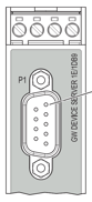
D-SUB9 to RS-485 Pin out
| D-SUB Pin | RS-485 |
| 2 | - |
| 3 | D(A) - Negative |
| 5 | GND |
| 7 | D(B) - Positive |
| 8 | - |
Typical Modbus Configurations
Note that the below are standard Modbus communication parameter setups. Some heat trace controllers have the ability to modify this but these are normally what they are.
|
Manufacture |
Controller Type |
Protocol Option |
Serial Setup (Baud Rate, Data Bits, Parity, Stop Bits) |
| nVent (Digitrace, Raychem) | 920 | Modbus RTU (serial) Modbus TCP (Ethernet) |
9600,8,N,2 |
| nVent (Digitrace, Raychem) | 910 | Modbus RTU (serial) Modbus TCP (Ethernet) |
9600,8,N,2 |
| nVent (Digitrace, Raychem) | NGC30 | Modbus RTU (serial) Modbus TCP (Ethernet) |
9600,8,N,2 |
| nVent (Digitrace, Raychem) | NGC40 | Modbus RTU (serial) Modbus TCP (Ethernet) |
9600,8,N,2 |
| nVent (Digitrace, Raychem) | T2000 | Modbus RTU (serial) Modbus TCP (Ethernet) |
9600,8,N,2 |
| nVent (Digitrace, Raychem) | Elexant 4010i | Modbus RTU (serial) Modbus TCP (Ethernet) |
9600,8,N,1 |
| Thermon | TC202/201/102/101 | Modbus ASCII | 9600,7,N,2 |
| Thermon | TCM2 | Modbus RTU | 9600,8,N,1 |
| Thermon | TC1818a | Modbus ASCII Modbus RTD |
9600,7,N,2 9600,8,N,1 |
| Thermon | TCM18 | Modbus ASCII Modbus RTD |
9600,7,N,2 9600,8,N,1 |
Modbus Polling Registers for Testing
|
Manufacture |
Controller Type |
Modbus Address | Function Code | Register | Value |
| nVent (Digitrace, Raychem) | 920 | Set on controller | 3 | 1 | |
| nVent (Digitrace, Raychem) | 910 | Set on controller | 3 | 1 | |
| nVent (Digitrace, Raychem) | NGC30 | Set on controller | 3 | 1 | |
| nVent (Digitrace, Raychem) | NGC40 | Set on controller | 3 | 1 | |
| nVent (Digitrace, Raychem) | T2000 | Set on controller | 3 | 1 | |
| nVent (Digitrace, Raychem) | Elexant 4010i | Set on controller | 3 | 1 | |
| Thermon | TC202/201/102/101 | Set on controller | 3 | 103 | Maintaint Temp CCT1 |
| Thermon | TCM2 | Set on controller | 3 | 2 | Maintaint Temp CCT1 |
| Thermon | TC1818a | Set on controller | 3 | 103 | Maintaint Temp CCT1 |
| Thermon | TCM18 | Set on controller | 3 | 366 | Maintaint Temp CCT1 |
nVent 920 Controllers utilize a Modbus address and a Sub Address.
Sub address 0 (zero), you will use the register number mentioned above. For every subaddress 512 is to be added to the register. Sub Address 0 = Register+0, Sub Address 1 = Register+512, Address 2 = Register+(512*2),
Depending on what Modbus Polling tool you use an offset of 1 may be required for the register number. Ex. If you aren't haveing luck increase the register number by 1.
Whenever polling an ACSII controller ensure the quantity of data bits your polling is always 1 bit.