
Purpose:
The following procedure is adding a new wireless RTD to the Genesis Control panel. Thermon currently uses the following third-party products for wireless RTD’s:
- Oleum – DH3 Gateway
- This device will be located at the heat trace control panel and will be the master gateway for any wireless RTD connected to it.
- Oleum – GP-TR81 – Wireless Transmitter
Resources
- Oleum-GP-TR81-Datasheet
- Oleum-GP-TR81 Guide
- GP-DH3-User Guide Datasheet
- GP-DH3-User Guide
- GP-TR81 - Firmware
- OleumTech-GP-Network-Configurator-Installer-v1.2.0
- Oleum - USB Cable Drivers
Connection Method:
The Genesis Controller will connect to the DH3 Gateway through it’s Ethernet port via a Modbus TCP/IP connection.
In theory, other wireless transmitters could be used as long as the Modbus map of the gateway is configured the same way as mentioned below.
Oleum makes a specific programming cable (Part# SX1000-CC2) that can be used to connect to the DH3 Gateway and connect to the wireless transmitters
- The best method of connecting to the DH3 Gateway is using an Ethernet cable (Modbus TCP/IP). No special cables needed
- You may use the Oleum USB cable to connect to the DH3 Gateway - You will require a specific driver to be installed. See the Resource Section.
- You will require the Oleum USB Cable to connect to the transmitters - No special drivers are required.
Dh3 Gateway - 10.0.0.10
Steps:
Oleum GP Network Configurator
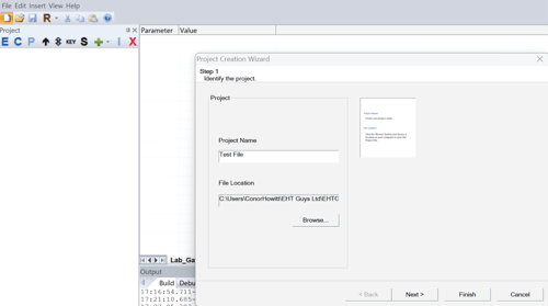
- Open the GP Network Configurator software and create a new project file.
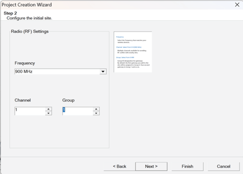
- Configure RF settings.
- Select the Frequency that matches the radio frequency of the wireless devices. Typically 900Mhz
- Select a Channel to avoid any RF conflict with any nearby sites.
- Select a Group - by default, the first gateway you add to the site will be assigned to 0. The second gateway added will be assigned 1 and so on.
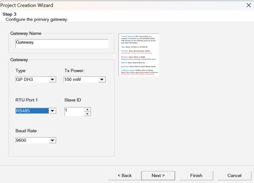
- Configure the primary wireless gateway.
- Create a Gateway Name.
- Select the Type (GP DH3).
- Select Tx Power – Selecting a higher transmit setting consumes more power.
- Select RTU Port 1 RS232 or RS485 (terminal block). – Not required
- Select Slave ID to 1
- Select Baud Rate that matches the Master device.
- Click Next.
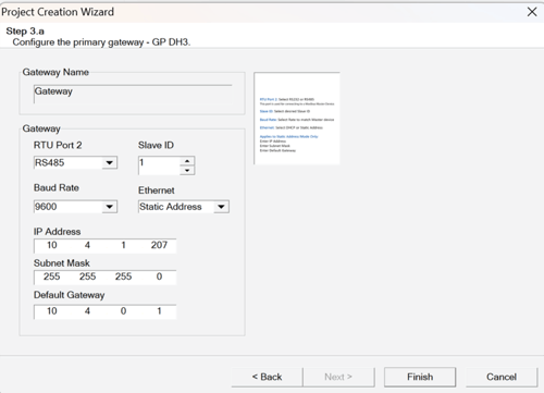
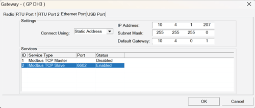
- Edit Ethernet and RTU port 2 settings (DH3 only).
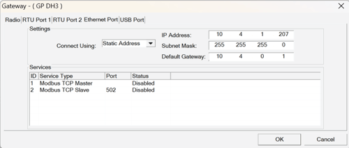
- Ethernet: Select the Static Address option.
- Enter in the IP Address to the device. – This address will be required at a later step
- Confirm project file settings.
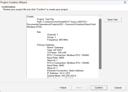
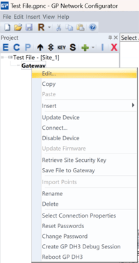
- Select the Gateway, right click and select “Edit”.
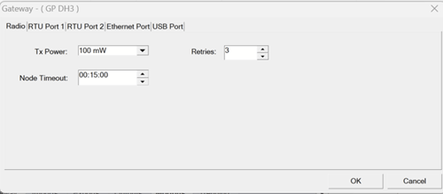
- Gateway Configuration – Radio Tab
- Tx Power – 100mW
- Retries – 3 – Typical
- Node Timeout 15min – Typical
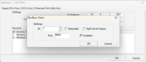
- Gateway Configuration – Ethernet Tab
- For ID 2 Modbus TCP Slave Set port to 6602 and Enable the port
- For ID 2 Modbus TCP Slave Set port to 6602 and Enable the port
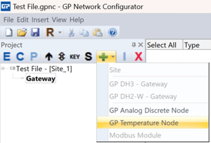
- Adding a Wireless Transmitter
- Select the Gateway and click the + button
- Select GP Temperature Node
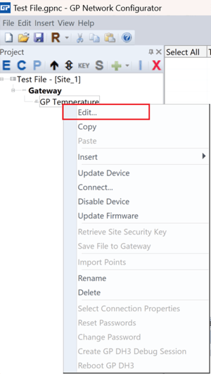
- Configuring the Wireless Transmitter
- Right click on the transmitter and select Edit
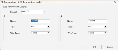
- Temperature Tab (Only RTD 1 will be used)
- Edit the Name of RTD1
- Change Type to RTD
- Wire Type -Typically 3-wire
- Interval time - 1:00 to 15 minutes
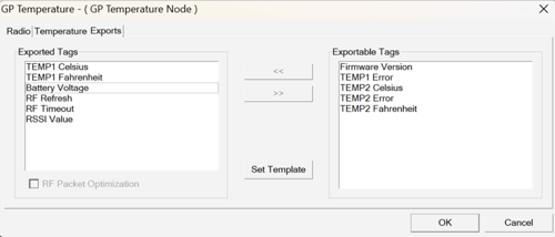
- Exports Tab - Ensure the Exported Tags match the below Image.
- Right click on the transmitter and select Edit
- Create the Modbus Registers for the Wireless RTD
- Select the Gateway and go to the Imports Tab
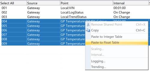
- Select the desired point
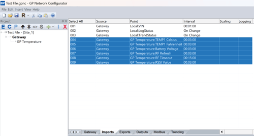
- Right-click over the selected points and select Float Table. (This will allow these points to be configured as Modbus register values
- Go to the Modbus tab and position the points in the following order for each wireless RTD - ensure the starting register number is 7001:
- Temp1 Fahrenheit
- Temp1 Celsius
- Battery Voltage
- RF Timeout
- RSSI Value
- RF Refresh
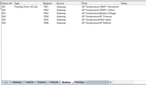
Note: for additional Wireless RTDs being added to the DH3 gateway they will be inserted below these Modbus registers in the same order. The order will dictate the RTD number in the Genesis controller.
- Write the transmitter configuration to the transmitter
- Supply power to the transmitter.
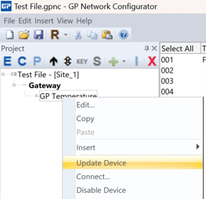
- Connect the PC to the transmitter using the Oleum configuration cable
- Right click on the Transmitter and select “Update Device”
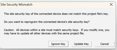
- If the transmitter was used with another project file, the Site Security Mismatch window will appear. Click Yes to proceed
- Upload the DH3 Configuration file to the DH3 Device - via the Ethernet connection.
- Connect the PC to the DH3 using an Ethernet cable.
Note: Ensure your computer IP address is set to static and in the same Subnet (IP address similar but not matching to the DH3 Device)
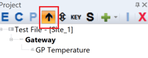
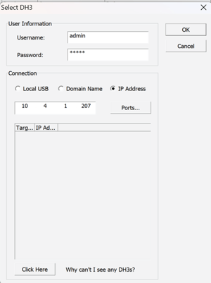
- Select the Gateway and Select Update Arrow
- Enter in the username and password (admin, admin)
- Select Connection type IP
- Enter in the IP address of the DH3 Device
- Click OK
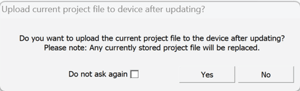
- Once uploaded the DH3 will ask if you want to upload the configuration file to the DH3. Click YES
Configuring the Genesis Controller
- Connect the PC to the DH3 using an Ethernet cable.
- Download the existing heat trace controller configuration file and open in Genesis Sync (Tracenet Sync). See here for details.
- Genesis Sync Configurations
-
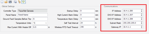
- In the Networking View
- Set the IP address for the first DH3 IP address that matches the DH3 Ip address
- Ensure the HMI IP address is in the same subnet as the DH3 Device
- In the Hardware View
- Go to the Device Tab and add a DH3 Device
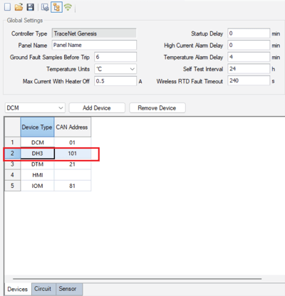
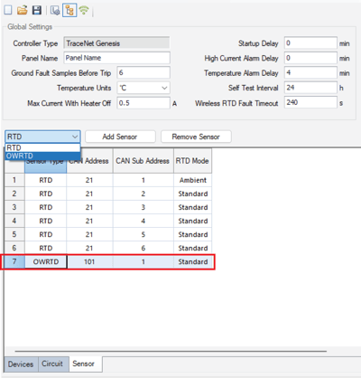
- Go to the Sensor Tab and add a OWRTD Device – Note the address 101 Sub address 1. (Where multiple RTD are connected to the DH3 device the Sub address will increment)
- Go to the Device Tab and add a DH3 Device
- In the Designer View
- Select the circuit that you want to have the wireless RTD connected to, right click and select Edit or Add
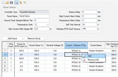
- Select the Wireless RTD
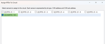
- Select the circuit that you want to have the wireless RTD connected to, right click and select Edit or Add
- In the Networking View
- Upload the new heat trace controller configuration file to the Genesis controller. See here for details.
When adding RTDs ensure you label the physical RTD. Once configured there is no identification in the configuration file to note which RTD is which.