Contents:
- Circuit Overview Page
- Circuit Details - Circuit Programming - Dashboard
- Circuit Details - Circuit Programming - Circuit Settings
- Assigning RTDs to Circuits
- Circuit Details - Circuit History
- Circuit Details - ISO (Isometrics)
- Alarm List
- Main Menu
- Admin Login
- Global Settings
- System Menu
Purpose:
This knowledge base serves as a comprehensive overview of all settings and programming capabilities available on the Genesis HMI (Human-Machine Interface). It provides users with detailed information and instructions to effectively navigate and utilize the features of the Genesis HMI for optimal performance and functionality.
Note:
Setting up a new Genesis Controller from scratch or during commissioning requires the use of the Genesis Sync (Tracenet Sync) application. This task cannot be completed solely on the panel HMI.
Similarly, when replacing or adding a new component to the Genesis control panel, the Genesis Sync (Tracenet Sync) application is necessary. Completing this activity solely on the panel HMI is not possible.
Genesis Controller HMI Screens
Circuit Overview Page
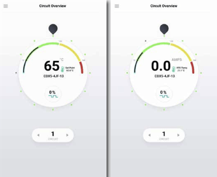
Get a quick snapshot of all circuits with a single glance, focusing on one circuit at a time for more detailed insight. Each dot encircling the selector dial represents a circuit, starting with Circuit 1 at the top and numbering ascending clockwise.
- Red dots: Alarmed circuits.
- Yellow dots: Alarms acknowledged.
- Green dots: Active circuits without alarms.
- Grey dots: Inactive circuits.
To navigate between circuits:
- Tap the circuit dot.
- Drag the black selector around the dial.
- Use the arrows flanking the circuit number.
The center of the dial showcases the highlighted circuit's live temperature, target temperature, circuit name, and on-off duty cycle. Tap anywhere inside the dial to access the dashboard for that circuit.
For circuits set for ambient control, a slightly different view emphasizes electrical current (amps) rather than current temperature. To switch to ambient control display, you need to identify the assigned ambient RTD through the RTD list in Global Settings.
Circuit Details - Circuit Programming - Dashboard
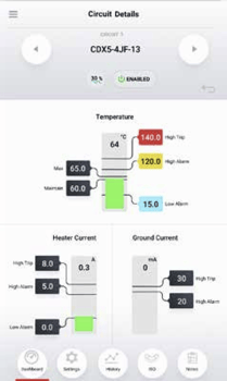
Experience a detailed view of individual circuits on the dashboard, featuring:
- Circuit number, tag, pipeline number, or other status.
- Real-time data on temperature, heater current, and ground leakage current.
- Alarm set points for quick reference.
Access this screen by tapping a circuit in the Overview or the Circuit List. The limits specified below outline the range of acceptable values. (These boundaries ensure valid settings, e.g., maintain temperature should not fall below the low temperature alarm threshold.)
Quick Programming:
Easily program the following setting simply by clicking the values from the Overview Screen
- Temperature:
- High Trip
- High Alarm
- Low Alarm
- Maintain Temperature
- Max Temp/Control Band
- Heater Current
- Low Alarm
- High Alarm/Trip
- Ground Current
- Alarm/Trip
Alarm Details
| Alarm Type | Description |
|---|---|
| RTD Fault Alarm | This alarm triggers when the RTD reading falls outside the acceptable range, indicated by a resistance value exceeding 313.7 Ohms or dropping below 48.46 Ohms. It suggests potential issues like an unconnected or faulty RTD. |
| Low Temperature Alarm | When the temperature on a circuit dips below the programmed threshold, this alarm activates. It automatically clears once the temperature rises back to normal. |
| High Temperature Alarm | Conversely, this alarm alerts when the temperature exceeds the set maximum. Similar to the low temp alarm, it clears once conditions return to normal. |
| High-High Temperature (Option Trip) | If temperatures soar beyond a preset limit, this alarm is triggered. Acknowledging the alarm and cooling the temperature below the threshold are necessary to re-energize the circuit. Enabling the trip option changes the alarm color to orange; otherwise, it clears automatically. |
| Ground Current High Alarm | Excessive ground/earth leakage current prompts this alarm. It clears once the high leakage current event subsides. |
| Ground Current High-High Alarm (Option Trip) | Similar to temperature, this alarm signifies extremely high ground/earth leakage current. Acknowledging the alarm and reducing the current below the threshold are essential for circuit re-energization. |
| Low Current Alarm | When circuit amperage drops below the acceptable level, this alarm triggers. |
| High Current Alarm | Conversely, this alarm activates when circuit amperage exceeds the maximum threshold. It clears automatically once current levels normalize. |
| High-High Current (Option Trip) | If current exceeds the preset limit, this alarm is triggered. Acknowledgment and reducing current below the threshold are necessary for re-energization. Enabling the trip option changes the alarm color to orange; otherwise, it clears automatically. |
| Circuit Fault Alarm | This alarm suggests potential circuit issues, including CAN bus communication interruption, damaged DCM board, or anomalies during the SELF-TEST procedure. |
| Ground Fault Alarm | During a TEST-TO-TRIP procedure, this alarm indicates a failure to sense test leakage current, signaling a ground fault condition. |
| Programming Error | This warning highlights conflicts in programmed values for temperature, current, and ground current. Properly setting the values ensures correct functionality. Note that despite this error, circuits may still activate, emphasizing the importance of addressing programming discrepancies promptly. |
| Setting | Description | Available Options | Lower Limit | Upper Limit | Units |
| Circuit Name | User defined Alpha-numeric Identifier unique to circuit | Alpha-numeric, Upper/ Lower Case, hyphen, dot | 1 | 50 | Characters |
| Process Tag | User defined alpha-numeric | ||||
| Identifier For Grouping Circuits Together By Associated Process | Alpha-numeric, Upper/Lower Case, hyphen, dot | 1 | Characters | ||
| Active Alarm | Hexadecimal code for active alarms and a button to display and acknowledge active alarms | Acknowledge individual alarms or acknowledge all alarms | 0x0000 | 0xFFFF | |
| Alarm Acknowledge | Hexadecimal code for active alarms and a button to display and acknowledge active alarms | Acknowledge individual alarms or acknowledge all alarms • When all alarms are acknowledged the alarm relay will reset regardless of the alarm condition | 0x0000 | 0xFFFF | |
| High Trip Settings | Enable or disable buttons for Temperature, Current and Ground Current trips | Enable/Disable • When a trip is enabled the alarm must be acknowledged to reset the circuit | |||
| Control Type | Chose control method for circuit | On/Off, On/Off with Soft-Start, Proportional, Ambient Proportional Control |
|||
| RTD Fault9 | Chose the forced duty cycle in the event of an RTD Fault | Number | 0 | 100 | % |
| Power Clamp10 | Maximum duty cycle allowed on circuit • Does not apply for Mechanical Relay | Number | 0 | 100 | % |
| Times The Heater Has Cycled11 | Cycle count for mechanical relay controlled by circuit | Number; read-only | 0 | 2,147,483,648 | Since Commissioning |
| Heater Relay Type | Displays mechanical or solid- state relays | Mechanical/SSR | Fixed at panel shop | ||
| Heater Voltage12 | Voltage provided to trace heater from relay(s) | Number | 0 | Fixed at panel shop | Volts |
| Heater Amp Hour Accumulation | Running total of Amp Hours accumulated since last reset of value | Number | 0 | 2,147,483,648 | |
| Heater Watt Hour Accumulation13 | Running total of Watts accumulated since last reset of value | Number | 0 | 2,147,483,648 | Watts |
| Time Heater Will Come Back On | Applies to APCM; time left until the heater switches on again within 20 minute window | Number | 0 | 20 | Minutes |
| Ground Current Reading At Trip | Ground fault current reading that caused most recent trip | Number | 20 | 255 | mA |
| Heater Current Reading At High Current Trip | Heater current reading that caused most recent trip | Number | 1 | 100 | A |
| DCM Address | Address (displayed on each board) unique to each board that allows communication between modules | Fixed number between 01-20 | 1 | Fixed at panel shop |
Notes:
9. RTD FAULT ALARM An RTD reading is out of range when the resistance exceeds 313 Ω or is less than 48 Ω. In either case, the RTD has been damaged or has been disconnected in service. NOTE: The Genesis Controller will continue to control if a second undamaged RTD is available. Otherwise, the default heater status is “De-energized”.
10. “Power Clamp” for Genesis Controller systems are available when the units are used with solid-state relays, and is enabled when a circuit is set for “on/off
with soft start”. This feature literally provides “soft start” using a reduced on/off duty time cycle of 1 second initiating at the percentage selected.
- Example 1: Power Clamp of 20% is selected this results in an initial duty cycle of 0.2s “full on” and 0.8s off)
- Example 2: “on/off with soft start” is selected with 100% Power Clamp. The result is that the circuit will operate in a normal on/off method.
12. The heat/voltage value is not measured by the Genesis Controller system. This value is fixed before panel shipment to match design and distribution voltage as constructed.
13. This value is calculated from supplied voltage and measured heater current.
Assigning RTDs to Circuits
Assigning RTDs to a circuit is a two-step process:
- Step 1 - Configure RTDs in Global Settings:
- RTDs need to be configured first in the global setting page using one of the following methods:
a. Standard Control Mode – Control/Alarm/Trip
b. Ambient - Control/Low Temp = DIS
c. Monitor Mode 1 – Alarm/Trip
d. Monitor Mode 2 – Trip
e. Monitor Mode 3 - Alarm
f. Monitor Mode 4 – Monitor Only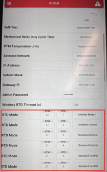
- RTDs need to be configured first in the global setting page using one of the following methods:
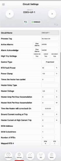
- Step 2 - Assign RTDs in Circuit Settings:
- Enter in the number of RTDs required for the circuit.
- Enter the CANBUS ID or the DTM that holds the desired RTDs into the "DTM" field,
- Enter in the RTD number (1-6) into the "RTD" field.
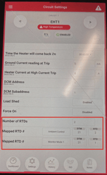
A single controller may have up to 20 RTDs assigned to it.
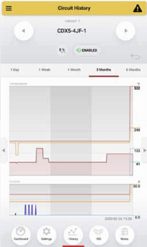
Circuit Details - Circuit History
Explore temperature and current data plotted over a span of up to six months, alongside recorded set point changes.
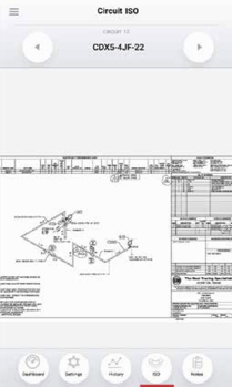
Circuit Details - ISO (Isometrics)
Easily inspect the circuit's isometric drawing (ISO) using multi-touch pinch and zoom gestures for a detailed view.
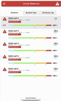
Alarm List
Access the Circuit Alarm List from the Menu. Here, live panes for each circuit in alarm are organized in a list with tabs for all alarms, categorized by alarm type, or by process. To acknowledge an alarm, simply tap "ACK" on the left of the circuit pane. A box will display each alarm for that circuit, allowing you to acknowledge individual alarms or all alarms for that circuit.
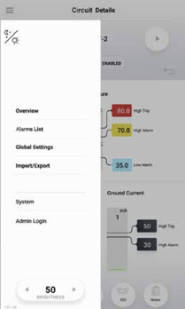
Main Menu
To access the Main Menu, simply tap the 'hamburger' icon located in the upper left corner of any screen. Use the Menu to effortlessly navigate between Overview, Circuit List, Global Settings, and the System screen. Additionally, you can switch between night and day color profiles and perform tasks like importing and exporting configurations, isometrics, and more.
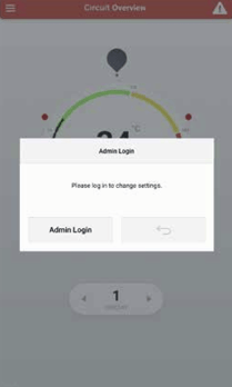
Admin Login
Note: The default "Admin Login" value is "abc123" (not case-sensitive). It's crucial to assign the "Admin Login" to the responsible Project Manager or Administrator overseeing the relevant process unit(s). This information should be securely stored but readily accessible in case of an emergency.
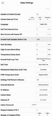
Global Settings:
Access Global Settings from the Menu. Here, you can configure system-wide settings such as Temperature Units and Start-up Delay, ensuring consistency across the entire system.
| Setting | Description | Acceptable | Lower Limit | Upper Limit | Units |
| System Date and Time | Current Time and Date | Gregorian Calendar; 24 hr time; time zone offset from GMT | |||
| Language | Displayed system language | English (US), English (UK), Arabic, Chinese, Spanish, French, Japanese, Korean, Russian | |||
| Self Test Interval (Hrs) | Time in hours between automatically run self tests | Number | 0 | 168 | Hours |
| Max Current with Heater Off | Maximum current reading allowed when a heater is off before a circuit fault alarm is triggered | Number | 0.5 | 5 | A |
| Ground Fault Samples Before Trip | Number of ground current samples read above trip set point before trip is triggered. (does not affect time to trip because the samples are microseconds apart) This is to improve noise immunity. | Number | 0 | 6 | |
| Start Up Delay | Time in minutes before heaters turn on for the first time after system power up. This allows users to stagger start up across many panels to reduce load step on plant power. | Number | 0 | 30 | Minutes |
| High Current Alarm Delay | Time in minutes to delay current alarms after high readings. This is to prevent nuisance alarms on startup current. | Number | 0 | 7 | Minutes |
| Temperature Delay Alarm | Time in minutes to delay temperature alarms. This is useful for avoiding nuisance alarms due to steam-out. | Number | 0 | 30 | Minutes |
| Ground Fault Loop Test | Runs self contained test to confirm integrity of the ground current measurement system. |
Touch to Start | |||
| Self-Test | Runs self contained test including the ground fault loop test and additionally turns measures heater current with heater on and off to verify relay operation and current measurements. | Touch to Start | |||
| Mechanical Relay Duty Cycle Time | Duty cycle period for relays in proportional control mode. | 20 Minutes | Minutes | ||
| DTM Temperature Units |
Switch temperature units between Fahrenheit and Celsius | Fahrenheit, Celsius | |||
| Settings Poll Period in Minutes | Time in minutes between requests from HMI to modules for all system information | Number | 5 | 20 | Minutes |
| Selected Network | Switch between Onboard Ethernet (default) or USB (for use with USB-Ethernet adapter - diagnostics) | Onboard/USB | |||
| IP Address | Internet Protocol Address (see network administrator for IP Address assignments) | IPv4 Address | 0.0.0.0 | 255.255.255.255 | |
| Subnet Mask | Binary mask which defines the subnetwork to which a device belongs (see network administrator for Subnet Mask assignments) | 0.0.0.0 | 255.255.255.255 | ||
| Gateway IP | First networking device connected to on the network (see network administrator for Gateway IP assignments) | IPv4 Address | 0.0.0.0 | 255.255.255.255 | |
| Admin Password | Password used to protect the system from unintended or unauthorized changes | Alpha-numeric 50 character limit | |||
| Number of Ambient RTDs | Sets the number of ambient RTD sensors used by the system | Number | 0 | 6 | |
| Mapped Ambient RTD# | Address and Subaddress of the assigned RTD; the number of "Mapped Ambient RTD#" fields corresponds to the "Number of Ambient RTDs" value, i.e. if "Number of Ambient RTDs" is set to 3, there will be 3 "Mapped Ambient RTD#" fields to provide an address for each RTD | DTM: number 1-99; RTD: Number 1-6 |
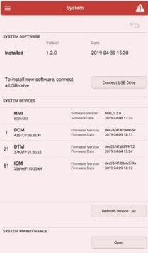
System Menu:
The System section offers tools for updating system software and firmware, displaying the current installed version. By selecting the "Mount USB Drive" button, users can access a list of all Genesis Controller modules, along with their respective addresses and firmware versions. Access to this section requires Admin Login for security purposes.